What kind of thread 1 8. Pipe thread sizes
GOST 6211-81
Group G13
INTERSTATE STANDARD
Basic norms of interchangeability
CONICAL PIPE THREAD
Basic norms of interchangeability. Pipe taper thread
Date of introduction 1983-01-01
1. DEVELOPED AND INTRODUCED by the Ministry of Machine Tool and Tool Industry
2. APPROVED AND ENTERED INTO EFFECT by Resolution of the USSR State Committee on Standards dated December 30, 1981 N 5789
3. INSTEAD GOST 6211-69
4. The standard fully complies with ST SEV 1159-78
5. REFERENCE REGULATIVE AND TECHNICAL DOCUMENTS
Item number |
|
Introductory part, 1.2, 3.3, 4.2 |
6. REISSUE
This standard applies to conical pipe threads with a taper of 1:16, used in conical threaded connections, as well as in connections of external conical threads with internal cylindrical threads with a profile in accordance with GOST 6357 and establishes the profile, main dimensions and tolerances of conical threads, as well as tolerances of internal cylindrical pipe thread connected to an external conical thread.
1. PROFILE
1. PROFILE
1.1. The nominal profile of the pipe conical thread (external and internal) and the dimensions of its elements must correspond to those indicated in Figure 1 and Table 1.
Damn.1. Nominal profile of pipe tapered thread (external and internal) and dimensions of its elements
Taper ; ; ; - outer diameter of the external tapered thread; - internal diameter of external tapered thread; - average diameter of external tapered thread; - outer diameter of the internal tapered thread; - internal diameter of the internal tapered thread; - average diameter of internal tapered thread; - thread pitch; - cone angle; - slope angle; - height of the original triangle; - working height of the profile; - radius of curvature of the top and bottom of the thread; - cutting off the tops and bottoms of the thread.
Table 1
Dimensions in millimeters
Number of steps per length 25.4 mm | |||||
Note. The numerical values of the steps are determined from the ratio with rounding to the third decimal place and taken as the initial ones when calculating the main elements of the profile.
1.2. The dimensions of the internal cylindrical thread profile elements are in accordance with GOST 6357.
2. MAIN DIMENSIONS
2.1. The designation of thread size, steps and nominal values of the main dimensions of conical (external and internal) threads must correspond to those indicated in Figure 2 and Table 2.
Damn.2. Designation of thread size, steps and nominal values of the main sizes of tapered (external and internal) threads
Working thread length; - length of external thread from end to main plane
table 2
Dimensions in millimeters
Designation | Thread diameters in the main plane | Thread length |
||||
Shorter thread lengths may be used.
2.2. Numerical values of diameters and are calculated using the following formulas
The numerical values of the diameter are established empirically.
2.3. The difference between the actual dimensions must be no less than the difference between the nominal dimensions and indicated in Table 2.
2.4. The length of the internal tapered thread must be at least 0.8 (where - in accordance with Table 3)*.
________________
* The text of the document corresponds to the original. - Database manufacturer's note.
Table 3
Dimensions in millimeters
Thread size designation | Offset of the main thread plane | Maximum deviations of the diameter of internal cylindrical threads |
|
2; 3; 3; 4; 5; 6 | |||
Note. Maximum deviations do not apply to threads with lengths shorter than those indicated in Table 2.
2.5. The designation of thread sizes, pitches and nominal values of the outer, middle and inner diameters of the internal cylindrical thread must correspond to those indicated in Figure 3 and Table 2.
Damn.3. Designation of thread sizes, pitches and nominal values of outer, middle and inner diameters of internal cylindrical threads
2.6. The design of parts with internal threads (conical and cylindrical) must ensure screwing in of external conical threads to a depth of at least .
3. TOLERANCES
3.1. The axial displacement of the main plane of the external and internal threads (Fig. 4) relative to the nominal location should not exceed the values specified in Table 3.
Damn.4. Axial displacement of the main plane of external and internal threads
Note. In the main plane, the average diameter has a nominal value.
The displacement of the main plane is total, including deviations of the average diameter, pitch, angle of inclination of the side of the profile and cone angle.
3.2. The maximum deviations of the average diameter of the internal cylindrical thread must correspond to those indicated in Table 3.
3.3. It is allowed to connect an external conical thread with an internal cylindrical thread of accuracy class A according to GOST 6357.
4. NOTATION
4.1. The thread designation must include: letters ( - for conical external threads, - for conical internal threads, - for cylindrical internal threads) and a designation of the thread size.
The symbol for left-hand threads is supplemented with the letters .
Examples of thread symbols:
- external pipe conical thread 1:
Internal pipe tapered thread 1:
Internal pipe straight thread 1:
Left hand thread:
4.2. A threaded connection is designated by a fraction, for example, or, the numerator of which indicates the letter designation of the internal thread, and the denominator - the external thread, and the thread size.
Examples of symbols for threaded connections:
- pipe conical thread (internal and external):
Internal pipe cylindrical thread (with tolerances according to this standard) and external pipe tapered thread:
Internal pipe cylindrical thread of accuracy class A according to GOST 6357 and external pipe conical thread:
APPENDIX (reference). LIMIT DEVIATIONS OF INDIVIDUAL THREAD PARAMETERS
APPLICATION
Information
1. This appendix contains information on the maximum deviations of individual thread parameters, which are the initial ones when designing a thread-forming tool and calculating thread gauges and are not subject to mandatory control, unless specifically stated.
2. The maximum deviations of the cut of the peaks and valleys (size), the angle of inclination of the side of the profile, the pitch and the cone angle (the difference in the average diameters along the length) of the conical thread are shown in Figure 1 and in the table.
Damn.1. Limit deviations of the cut of the peaks and valleys, the angle of inclination of the side of the profile, the pitch and the angle of the cone
es - upper deviation of the cut of the top and bottom of the external thread; ES - upper deviation of the cut of the top and bottom of the internal thread; ei - lower deviation of the cut of the top and bottom of the external thread; EI - lower deviation of the cut of the top and bottom of the internal thread; - tolerance of the angle of inclination of the side of the thread profile.
3. The maximum deviations of the cut of the peaks and valleys (size) of the internal cylindrical thread (Fig. 2) should not exceed:
- cut of vertices +0.05 mm (ES=+0.05 mm, EI=0);
- cut of depressions ±0.025 mm (ES=+0.025 mm, EI=-0.025 mm)
Damn.2. Limit deviations for cutting the tops and bottoms of internal cylindrical threads
Dimensions in millimeters
Thread size designation | Prev. off | Average diameter difference |
||||||||
step on length | ||||||||||
peaks | depressions | Prev. off |
||||||||
external thread | internal thread |
|||||||||
0,028 | 0,014 |
|||||||||
0,042 | 0,021 |
|||||||||
0,044 | 0,022 |
|||||||||
0,058 | 0,028 |
|||||||||
0,066 | 0,034 |
|||||||||
0,073 | 0,036 |
|||||||||
0,089 | 0,045 |
|||||||||
0,111 | 0,056 |
|||||||||
0,122 | 0,062 |
|||||||||
0,073 |
||||||||||
0,155 | 0,078 |
|||||||||
0,177 | 0,089 |
|||||||||
0,200 | 0,101 |
|||||||||
Note. The value refers to the distances between threads. The actual deviation may have a minus or plus sign.
Electronic document text
prepared by Kodeks JSC and verified against:
official publication
Inch and special threads: Sat. GOST. -
M.: IPK Standards Publishing House, 2003
MAIN DIMENSIONS
PIPE TAPER THREAD
(GOST 6211-81)
The standard applies to tapered pipe threads with a taper 1: 16 . used in conical threaded connections, as well as in connections of external conical threads with internal cylindrical threads with a profile in accordance with GOST 6357-81.
Taper 2tg(φ /2) = 1: 16;
φ = 3°34"48"; φ/2 = 1°47"24";
d and D are the outer diameters of the external and internal threads, respectively;
d 1 and D 1 - internal diameters of external and internal threads, respectively;
d 2 and D 2 - average diameters of external and internal threads, respectively;
P - thread pitch;
φ - cone angle; φ/2 - slope angle;
H - height of the original triangle;
H 1 - working height of the profile;
R - radius of curvature of the top and bottom of the thread;
C - cut of the tops and bottoms of the thread;
l 1 - working length threads;
l 2- the length of the external thread from the end to the main plane.
dimensions, mm
| Thread size designation | Step P | Number of steps per length 25.4 mm | H | H 1 | C | R | Thread diameters in the main plane | Thread length | |||
| d = D | d2 = D2 | d 1 = D 1 | l 1 | l 2 | |||||||
| 1/16" | 0,907 | 28 | 0,870935 | 0,580777 | 0,145079 | 0,124511 | 7,723 | 7,142 | 6,561 | 6,5 | 4,0 |
| 1/8" | 9,728 | 9,147 | 8,566 | ||||||||
| 1/4" | 1,337 | 19 | 1,283837 | 0,856117 | 0,213860 | 0,183541 | 13,157 | 12,301 | 11,445 | 9,7 | 6,0 |
| 3/8" | 16,662 | 15,806 | 14,950 | 10,1 | 6,4 | ||||||
| 1/2" | 1,814 | 14 | 1,741870 | 1,161553 | 0,290158 | 0,249022 | 20,955 | 19,793 | 18,631 | 13,2 | 8,2 |
| 3/4" | 26,441 | 25,279 | 24,117 | 14,5 | 9,5 | ||||||
| 1" | 2,309 | 11 | 2,217187 | 1,478515 | 0,369336 | 0,316975 | 33,249 | 31,770 | 30,291 | 16,8 | 10,4 |
| 1 1/4" | 41,910 | 40,431 | 38,952 | 19,1 | 12,7 | ||||||
| 1 1/2" | 47,803 | 46,324 | 44,845 | ||||||||
| 2" | 59,614 | 58,135 | 56,656 | 23,4 | 15,9 | ||||||
| 2 1/2" | 75,184 | 73,705 | 72,226 | 26,7 | 17,5 | ||||||
| 3" | 87,884 | 86,405 | 84,926 | 29,8 | 20,6 | ||||||
| 3 1/2" | 100,330 | 98,851 | 97,372 | 31,4 | 22,2 | ||||||
| 4" | 113,030 | 111,551 | 110,072 | 35,8 | 25,4 | ||||||
| 5" | 138,430 | 136,951 | 135,472 | 40,1 | 28,6 | ||||||
| 6" | 163,830 | 162,351 | 160,872 | ||||||||
DESIGNATION
The thread designation must include: letters (R - for tapered external threads, R c - for tapered internal threads, R p - for cylindrical internal threads) and a designation of the thread size:
external pipe tapered thread - R 1 1/2
internal pipe conical thread - R with 1 1/2
internal pipe cylindrical thread - R p 1 1/2
left thread - R 1 1/2LH, R with 1 1/2LH, R p 1 1/2LH.
A threaded connection is designated by a fraction, for example Rc/R or Rp/R in the numerator of which the letter designation of the internal thread is indicated, and in the denominator - the external thread and the thread size.
For example: R with /R 1 1/4LH.
TOLERANCES OF PIPE TAPER THREAD
(GOST 6211-81)
dimensions, mm
| Thread profile | Designation size threads | Offset of the main thread plane | Limit deviations diameter internal cylindrical threads |
|
| ±Δ 1 l 1 | ±Δ 2 l 2 | |||
 | 1/16" | 0,9 | 1,1 | ±0.071 |
| 1/8" | ||||
| 1/4" | 1,3 | 1,7 | ±0.104 | |
| 3/8" | ||||
| 1/2" | 1,8 | 2,3 | ±0.142 | |
| 3/4" | ||||
| 1" | 2,3 | 2,9 | ±0.180 | |
| 1 1/4" | ||||
| 1 1/2" | ||||
| 2" | ||||
| 2 1/2" | 3,5 | 3,5 | ±0.217 | |
| 3" | ||||
| 3 1/2" | ||||
| 4" | ||||
| 5" | ||||
| 6" | ||||
| In the main plane, the average diameter has a nominal value. | ||||
| Note. The maximum deviation ±Δ 1 l 1 and ±Δ 2 l 2 does not apply to threads with lengths shorter than those indicated in the first table. | ||||
Shorter thread lengths may be used.
Difference between actual sizes l 1 - l 2 must be no less than the difference in nominal sizes l 1 And l 2 indicated in the first table.
Related documents:
GOST 3469-91 - Microscopes. Lens thread. Dimensions
GOST 4608-81 - Metric thread. Preference fits
GOST 5359-77 - Eyepiece thread for optical instruments. Profile and dimensions
GOST 6042-83 - Edison round thread. Profiles, dimensions and limits
GOST 6111-52 - Conical inch thread with a profile angle of 60 degrees
GOST 6211-81 - Tapered pipe thread
GOST 6357-81 - Cylindrical pipe thread
GOST 8762-75 - Round thread with a diameter of 40 mm for gas masks and calibers for it. Main Dimensions
GOST 9000-81 - Metric threads for diameters less than 1 mm. Tolerances
GOST 9484-81 - Trapezoidal thread. Profiles
GOST 9562-81 - Single-start trapezoidal thread. Tolerances
GOST 9909-81 - Tapered thread of valves and gas cylinders
GOST 10177-82 - Persistent thread. Profile and main dimensions
GOST 11708-82 - Thread. Terms and Definitions
GOST 11709-81 - Metric thread for plastic parts
GOST 13535-87 - Reinforced thrust thread 45 degrees
GOST 13536-68 - Round thread for sanitary fittings. Profile, main dimensions, tolerances
GOST 16093-2004 - Metric thread. Tolerances. Landings with clearance
GOST 16967-81 - Metric threads for instrument making. Diameters and pitches
GOST 24737-81: Single-start trapezoidal thread. Main Dimensions
GOST 24739-81 - Multi-start trapezoidal thread
GOST 25096-82 - Persistent thread. Tolerances
GOST 25229-82 - Metric tapered thread
GOST 28487-90: Conical locking threads for drill string elements. Profile. Dimensions. Tolerances
Date of introduction 01.01.83
This standard applies to conical pipe threads with a taper of 1:16, used in conical threaded connections, as well as in connections of external conical threads with internal cylindrical threads with a profile in accordance with GOST 6357 and establishes the profile, main dimensions and tolerances of conical threads, as well as tolerances of internal cylindrical pipe thread connected to an external conical thread.
1. PROFILE
1.1. The nominal profile of the pipe conical thread (external and internal) and the dimensions of its elements must correspond to those indicated in the drawing. 1 and in table. 1.
|
Taper ;j =3 ° 34 ¢ 48 ¢ ¢ ; ; d- outer diameter of the external tapered thread; d 1 - internal diameter of external tapered thread; d 2 - average diameter of external tapered thread; D- outer diameter of the internal tapered thread; D 1 - internal diameter of the internal tapered thread; D 2 - average diameter of internal tapered thread; R- thread pitch; j - cone angle;j /2 - slope angle; H- height of the original triangle; H 1 - working height of the profile; R- radius of curvature of the top and bottom of the thread; WITH- cutting off the tops and bottoms of the thread. Crap. 1 |
Table 1
Dimensions in millimeters
|
Step R |
Number of steps z at a length of 25.4 mm |
H = 0,960237P |
H 1 = 0,640327P |
C = 0.159955 R |
R = 0,137278R |
|
0,907 |
0,870935 |
0,580777 |
0,145079 |
0,124511 |
|
|
1,337 |
1,283837 |
0,856117 |
0,213860 |
0,183541 |
|
|
1,814 |
1,741870 |
1,161553 |
0,290158 |
0,249022 |
|
|
2,309 |
2,217187 |
1,478515 |
0,369336 |
0,316975 |
Note . The numerical values of the steps are determined from the relation R = 25,4/z rounded to the 3rd decimal place and taken as the initial ones when calculating the main profile elements.
1.2. The dimensions of the internal cylindrical thread profile elements are in accordance with GOST 6357.
2. MAIN DIMENSIONS
2.1. The designation of thread size, pitches and nominal values of the main dimensions of conical (external and internal) threads must correspond to those indicated in the drawing. 2 and in table. 2.
Shorter thread lengths may be used.

l 1 - working thread length; l 2 - length of external thread from the end to the main plane.
Crap. 2
Table 2
Dimensions in millimeters
|
Thread size designation |
Step R |
Thread diameters in the main plane |
Thread length |
|||
|
d = D |
d 2 = D 2 |
d 1 = D 1 |
l 1 |
l 2 |
||
|
1 / 16 |
0,907 |
7,723 |
7,142 |
6,561 |
||
|
1 / 8 |
9,728 |
9,147 |
8,566 |
|||
|
1 / 4 |
1,337 |
13,157 |
12,301 |
11,445 |
||
|
3 / 8 |
16,662 |
15,806 |
14,950 |
10,1 |
||
|
1 / 2 |
1,814 |
20,955 |
19,793 |
18,631 |
13,2 |
|
|
3 / 4 |
26,441 |
25,279 |
24,117 |
14,5 |
||
|
2,309 |
33,249 |
31,770 |
30,291 |
16,8 |
10,4 |
|
|
1 1 / 4 |
41,910 |
40,431 |
38,952 |
19,1 |
12,7 |
|
|
1 1 / 2 |
47,803 |
46,324 |
44,845 |
|||
|
59,614 |
58,135 |
56,656 |
23,4 |
15,9 |
||
|
2 1 / 2 |
75,184 |
73,705 |
72,226 |
26,7 |
17,5 |
|
|
87,884 |
86,405 |
84,926 |
29,8 |
20,6 |
||
|
3 1 / 2 |
100,330 |
98,851 |
97,372 |
31,4 |
22,2 |
|
|
113,030 |
111,551 |
110,072 |
35,8 |
25,4 |
||
|
138,430 |
136,951 |
135,472 |
40,1 |
28,6 |
||
|
163,830 |
162,351 |
160,872 |
||||
2.2. Numerical diameters d 2 and d 1 is calculated using the following formulas
d 2 = D 2 = d - 0,640327 P,(1)
d 1 = D 1 = d - 1,280654 P.(2)
Diameter numbers d established empirically.
2.3. Difference between actual sizes l 1 - l 2 must be at least the difference in nominal sizes l 1 and l 2 indicated in table. 2.
2.4. The length of the internal tapered thread must be at least 0.8 ( l 1 - D 1 l 2), where D 1 l 2 - in accordance with table. 3.
Table 3
Dimensions in millimeters
|
Thread size designation |
Offset of the main thread plane |
Maximum diameter deviations D 2 internal cylindrical threads |
|
|
±D 1 l 2 |
±D 2 l 2 |
||
|
1 / 16 |
±0.071 |
||
|
1 / 8 |
|||
|
1 / 4 |
±0.104 |
||
|
3 / 8 |
|||
|
1 / 2 |
±0.142 |
||
|
3 / 4 |
|||
|
±0.180 |
|||
|
1 1 / 4 |
|||
|
1 1 / 2 |
|||
|
2 1 / 2 |
±0.217 |
||
|
3 1 / 2 |
|||
Note . Limit deviations± D 1 l 2 and ± D 2 l 2 do not apply to threads with lengths shorter than those indicated in the table. 2.
2.5. The designation of thread sizes, pitches and nominal values of the outer, middle and inner diameters of the internal cylindrical thread must correspond to those indicated in the drawing. 3 and in table. 2.

2.6. The design of parts with internal threads (conical and cylindrical) must ensure screwing in external conical threads to a depth of at least l 1 + D 1 l 2 .
3. TOLERANCES
3.1. Axial displacement of the main plane D 1 l 2 outdoor and D 2 l 2 internal threads (Fig. 4) relative to the nominal location should not exceed the values specified in table. 3.
The displacement of the main plane is total, including deviations of the average diameter, pitch, angle of inclination of the side of the profile and cone angle.
3.2. The maximum deviations of the average diameter of the internal cylindrical thread must correspond to those indicated in the table. 3.

Crap. 4
Note . In the main plane, the average diameter has a nominal value.
3.3. It is allowed to connect an external conical thread with an internal cylindrical thread of accuracy class A according to GOST 6357.
4. NOTATION
4.1. The thread symbol must include: letters ( R- for tapered external threads, Rc - for tapered internal threads, Rp- for cylindrical internal threads) and thread size designation.
The symbol for left-hand threads is supplemented with letters L.H.
Examples of thread designations:
Male Pipe Taper Thread 1 1/2:
R 1 1 / 2
1 1/2 Internal Pipe Taper Thread:
Rc 1 1 / 2
Internal pipe straight thread 1 1/2:
R P 1 1 / 2
Left hand thread:
R 1 1 / 2 L.H.;
Rc 1 1 / 2 L.H.;
R P 1 1 / 2 L.H.
4.2. A threaded connection is designated by a fraction, for example, or Rc/R, the numerator of which indicates the letter designation of the internal thread, and the denominator - the external thread, and the thread size.
Notation examples threaded connection:
Pipe conical thread (internal and external);
Internal pipe cylindrical thread (with tolerances according to this standard) and external pipe tapered thread:
Internal pipe cylindrical thread of accuracy class A according to GOST 6357 and external pipe conical thread:
![]()
APPLICATION
Information
LIMIT DEVIATIONS OF INDIVIDUAL THREAD PARAMETERS
1. This appendix contains information on the maximum deviations of individual thread parameters, which are the initial ones when designing a thread-forming tool and calculating thread gauges and are not subject to mandatory control, unless specifically stated.
2. Limit deviations of cutting peaks and valleys (size WITH), angle of inclination of the side of the profile, pitch R and cone angle j(difference in average diameters along the length l 2) conical threads are shown in Fig. 1 and in the table.

Dimensions in millimeters
|
Thread size designation |
Limit deviations |
Difference in average thread diameters over length l 2 |
|||||||||
|
cut WITH |
angle a/2 |
step R at length |
|||||||||
|
Nom. |
Limit deviations |
||||||||||
|
peaks |
depressions |
l 2 |
l 1 |
||||||||
|
es = ES |
ei = EI |
es = ES |
ei = EI |
T P |
external thread |
internal thread |
|||||
|
1 / 16 ; |
0,05 |
0,025 |
0,025 |
40 ¢ |
0,04 |
0,07 |
0,250 |
0,028 |
0,014 |
||
|
1 / 8 |
0,014 |
0,028 |
|||||||||
|
1 / 4 |
35 ¢ |
0,375 |
0,042 |
0,021 |
|||||||
|
0,021 |
0,042 |
||||||||||
|
3 / 8 |
0,400 |
0,044 |
0,022 |
||||||||
|
0,022 |
0,044 |
||||||||||
|
1 / 2 |
0,512 |
0,058 |
0,028 |
||||||||
|
0,028 |
0,058 |
||||||||||
|
3 / 4 |
0,594 |
0,066 |
0,034 |
||||||||
|
0,034 |
0,066 |
||||||||||
|
25 ¢ |
0,650 |
0,073 |
0,036 |
||||||||
|
0,036 |
0,073 |
||||||||||
|
1 1 / 4 ; |
0,794 |
0,089 |
0,045 |
||||||||
|
1 1 / 2 |
0,045 |
0,090 |
|||||||||
|
0,994 |
0,111 |
0,056 |
|||||||||
|
0,056 |
0,111 |
||||||||||
|
2 1 / 2 |
1,094 |
0,122 |
0,062 |
||||||||
|
0,062 |
0,122 |
||||||||||
|
1,288 |
0,144 |
0,073 |
|||||||||
|
0,073 |
0,144 |
||||||||||
|
3 1 / 2 |
1,388 |
0,155 |
0,078 |
||||||||
|
0,078 |
0,155 |
||||||||||
|
1,588 |
0,177 |
0,089 |
|||||||||
|
0,089 |
0,177 |
||||||||||
|
1,788 |
0,200 |
0,101 |
|||||||||
|
0,101 |
0,200 |
||||||||||
Note . T value R refers to the distances between threads. The actual deviation may have a minus or plus sign.
3. Limit deviations of the cut of the peaks and valleys (size) of the internal cylindrical thread (Fig. 2) should not exceed:
Vertex cut +0.05 mm (ES = +0.05 mm, EI = 0);
Cutting depressions ± 0.025 mm (ES = +0.025 mm, EI = -0.025 mm)

INFORMATION DATA
1. DEVELOPED AND INTRODUCED by the Ministry of Machine Tool and Tool Industry
2. APPROVED AND ENTERED INTO EFFECT by Resolution of the USSR State Committee for Standards dated December 30, 1981 No. 5789.
3. INSTEAD GOST 6211-69
4. The standard fully complies with ST SEV 1159-78
5. REFERENCE REGULATIVE AND TECHNICAL DOCUMENTS
6. REISSUE
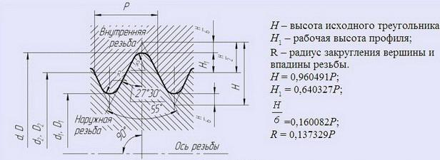
Straight pipe threads are mainly used for pipe connections, pipeline fittings and fittings. This thread covers diameters from 1/16 to 6" with a number of threads per 1" from 28 to 11.
Nominal diameter pipe thread conditionally referred to the internal diameter of the pipe. In terms of the ratio of pitches and diameters, pipe thread is a crushed inch thread according to OST 1260. Therefore, pipe thread at one time, before the standardization of small metric threads, was used not only for pipe connections, but also for fasteners, when there was a need to make threads with relatively in small steps, with large diameters. Pipe thread is a pan-European standard for pipes and pipe connections.
STRAIGHT PIPE THREAD DIMENSIONS
(GOST 6357-81)
The standard applies to cylindrical pipe threads used in cylindrical threaded connections, as well as in connections of internal cylindrical threads with external conical threads in accordance with GOST 6211-81.
Tolerances (according to GOST 6357-81) of the average thread diameter are established in two accuracy classes - A and B. Tolerances of the average thread diameter are total. Tolerances for diameters d 1 and D are not established.
dimensions, mm
| Thread designation | Number of steps z at a length of 25.4 mm | Step P | Thread diameter | Working height of profile H 1 | Curvature radius R | H | H/6 | |||
| 1st row | 2nd row | outer d = D | average d 2 = D 2 | internal d 1 = D 1 | ||||||
| 1/16" 1/8" | - | 28 | 0,907 | 7,723 | 7,142 | 6,561 | 0,580777 | 0,124557 | 0,871165 | 0,145194 |
| 9,728 | 9,147 | 8,566 | ||||||||
| 1/4" 3/8" | - | 19 | 1,337 | 13,157 | 12,301 | 11,445 | 0,856117 | 0,183603 | 1,284176 | 0,214029 |
| 16,662 | 15,806 | 14,950 | ||||||||
| 1/2" | 5/8" | 14 | 1,814 | 20,955 | 19,793 | 18,631 | 1,161553 | 0,249115 | 1,742331 | 0,290389 |
| 22,911 | 21,749 | 20,587 | ||||||||
| 26,441 | 25,279 | 24,117 | ||||||||
| 30,201 | 29,039 | 27,877 | ||||||||
| 1" | 1 1/8" 1 3/4" | 11 | 2,309 | 33,249 | 31,770 | 30,291 | 1,478515 | 0,317093 | 2,217774 | 0,369629 |
| 37,897 | 36,418 | 34,939 | ||||||||
| 41,910 | 40,431 | 38,952 | ||||||||
| 44,323 | 42,844 | 41,365 | ||||||||
| 47,803 | 46,324 | 44,845 | ||||||||
| 53,746 | 52,267 | 50,788 | ||||||||
| 59,614 | 58,135 | 56,656 | ||||||||
| 2 1/2" 3 1/2" | 2 1/4" 3 3/4" |
65,710 | 64,231 | 62,752 | ||||||
| 75,184 | 73,705 | 72,226 | ||||||||
| 81,534 | 80,055 | 78,576 | ||||||||
| 87,884 | 86,405 | 84,926 | ||||||||
| 93,980 | 92,501 | 91,022 | ||||||||
| 100,330 | 98,851 | 97.372 | ||||||||
| 106,680 | 105,201 | 103,722 | ||||||||
| 4" | 4 1/2" 5 1/2" |
113,030 | 111,551 | 110.072 | ||||||
| 125,730 | 124,251 | 122,772 | ||||||||
| 138,430 | 136,951 | 135,472 | ||||||||
| 151,130 | 149,651 | 148,172 | ||||||||
| 163,830 | 162,351 | 160,872 | ||||||||
| When choosing thread sizes, row 1 should be preferred to row 2. | ||||||||||
MAKE-UP LENGTHS according to GOST 6357-81
Make-up lengths are divided into two groups: normal N and long L.
dimensions, mm
| Designation thread size | Step P | Make-up length | |
| N | L | ||
| 1/16", 1/8" | 0,907 | St. 4 to 12 | St. 12 |
| 1/4", 3/8" | 1,337 | St. 5 to 16 | St. 16 |
| 1/2", 5/8" | 1,814 | St. 7 to 22 | St. 22 |
| 1", 1 1/8", 1 1/4", 1 3/8" | 2,309 | St. 10 to 30 | St. thirty |
| 1 1/2", 1 3/4", 2", 2 1/4", 2 1/2", 2 3/4", 3" | St. 12 to 36 | St. 36 | |
| 3 1/4", 3 1/2", 3 3/4", 4", 4 1/2", 5", 5 1/2", 6" | St. 13 to 40 | St. 40 | |
| Numerical values of make-up lengths are established empirically. | |||
The symbol for left-hand threads is supplemented with the letters LH.
Examples symbol thread accuracy class A:
G 1 1/2-A
left-hand thread accuracy class B:
G 1 1/2 LH-B
The make-up length N is not indicated in the thread designation.
The make-up length L is indicated in millimeters.
G 1 1/2 LH-B-40
The fit is indicated by a fraction: the numerator of which indicates the designation of the accuracy class of the internal thread, and the denominator indicates the designation of the accuracy class of the external thread.
G 1 1/2-A/A; G 1 1/2 LH-A/B
The connection of an internal pipe cylindrical thread of accuracy class A according to this standard with an external pipe conical thread in accordance with GOST 6211-81 is designated as follows:
G/R 1 1/2 - A
P.S. At one time, the profile of cylindrical pipe threads (according to OST 266) extended to diameters up to 18" with the number of threads per 1" from 28 to 8.
Related documents:
- holes for threading
GOST 3469-91 - Microscopes. Lens thread. Dimensions
GOST 4608-81 - Metric thread. Preference fits
GOST 5359-77 - Eyepiece thread for optical instruments. Profile and dimensions
GOST 6042-83 - Edison round thread. Profiles, dimensions and limits
GOST 6111-52 - Conical inch thread with a profile angle of 60 degrees
GOST 6211-81 - Tapered pipe thread
GOST 6357-81 - Cylindrical pipe thread
GOST 8762-75 - Round thread with a diameter of 40 mm for gas masks and calibers for it. Main Dimensions
GOST 9000-81 - Metric threads for diameters less than 1 mm. Tolerances
GOST 9484-81 - Trapezoidal thread. Profiles
GOST 9562-81 - Single-start trapezoidal thread. Tolerances
GOST 9909-81 - Tapered thread of valves and gas cylinders
GOST 10177-82 - Persistent thread. Profile and main dimensions
GOST 11708-82 - Thread. Terms and Definitions
GOST 11709-81 - Metric thread for plastic parts
GOST 13535-87 - Reinforced thrust thread 45 degrees
GOST 13536-68 - Round thread for sanitary fittings. Profile, main dimensions, tolerances
GOST 16093-2004 - Metric thread. Tolerances. Landings with clearance
GOST 16967-81 - Metric threads for instrument making. Diameters and pitches
GOST 24737-81: Single-start trapezoidal thread. Main Dimensions
GOST 24739-81 - Multi-start trapezoidal thread
GOST 25096-82 - Persistent thread. Tolerances
GOST 25229-82 - Metric tapered thread
GOST 28487-90: Conical locking threads for drill string elements. Profile. Dimensions. Tolerances
